
Directional overcurrent protection is one of those topics that clicks once you understand an overcurrent relay.
An ordinary overcurrent relay is a one-dimensional device. It measures how much current is flowing and trips when that magnitude exceeds a threshold for long enough. What it cannot tell you which way the current is flowing. On a simple radial feeder fed from one end, that limitation costs nothing. Because fault current can only come from one direction. But the moment you introduce sources at both ends, parallel feeders, or a ring main, magnitude alone becomes ambiguous. Current of the same size can flow toward a fault that your relay should clear, or away from a fault that a different relay should clear. Trip on the wrong one and you disconnect healthy load.
Directional overcurrent protection resolves the ambiguity by adding a second dimension. A directional element that decides whether a fault lies in the forward (protected) direction or the reverse direction. And only then permits the overcurrent element to operate.
This article walks through the directional principle. In detail, the different polarization methods: self, cross, zero-sequence and negative-sequence. These methods make the directional decision reliable under real fault conditions. A complete numerical worked example ties the theory back to measurable phasors.
How Direction is Determined?
Direction is determined by measuring the phase angle between two quantities:
- an operating quantity, normally the fault current seen by the relay, and
- a polarizing (reference) quantity, normally a voltage that stays reasonably stable and whose angular position is known.
For a forward fault, the current lags its driving voltage by the impedance angle of the fault loop typically 60° to 85° for overhead transmission and sub-transmission lines. For a reverse fault the current is displaced by roughly 180° from that position. The relay is configured with a Relay Characteristic Angle (RCA), called the Maximum Torque Angle (MTA) in the electromechanical era. The RCA defines the direction, relative to the polarizing quantity, in which the operating current produces the strongest operating tendency. A forward decision is declared when the current falls within approximately ±90° of the RCA line; the edge of that half-plane is the zero-torque line.
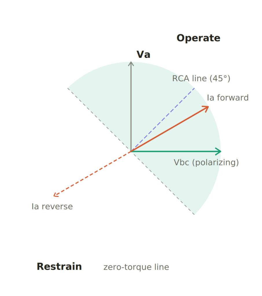
Figure 1 indicates the directional plane. The polarizing voltage Vbc sets the reference; advancing it by the RCA (here 45°) forms the maximum-torque line. A forward fault current sits inside the shaded operate half-plane; a reverse current, roughly 180° away, falls in the restrain region.
The entire craft of polarization comes down to choosing a reference quantity that satisfies two competing requirements at once. First one is it must give the correct angular relationship for every fault type. And then second one is critically it must remain healthy enough to measure during the fault. That second requirement is what separates the polarization schemes described below.
Self Polarization
The most intuitive scheme polarizes each phase current element with its own phase voltage. The A-phase current is referenced to Va, the B-phase current to Vb, and the C-phase current to Vc.
The weakness is fundamental. For a close-in fault on a given phase, the voltage of that same phase at the relay location collapses toward zero. Precisely when the relay most needs to make a direction decision a solid nearby fault, its reference disappears. Notice figure 3, fault occurs in phase A and then its reference voltage Va almost disappear.
Electromechanical relays produced almost no operating torque in this condition. Where numerical relays flag the polarizing voltage as too small to trust. The result is a directional dead zone for close-in faults, sometimes called close-in fault blindness. Because of this, pure self-polarization is rarely used on its own for phase-fault directional elements.
Cross Polarization
The fix that dominates practical phase-fault relaying is to reference each faulted-phase current to a voltage derived from the healthy (unfaulted) phases, which stay close to normal during a single-phase fault. Cross-polarization exploits the fact that a fault on one phase barely disturbs the voltage between the other two phases.
The 90° (quadrature) connection
In the standard quadrature scheme each phase current is paired with the line-to-line voltage of the two other phases:
- Ia is polarized by Vbc
- Ib is polarized by Vca
- Ic is polarized by Vab
Under balanced conditions each of these polarizing voltages lags its corresponding phase voltage by exactly 90°, which is where the “quadrature” name comes from.
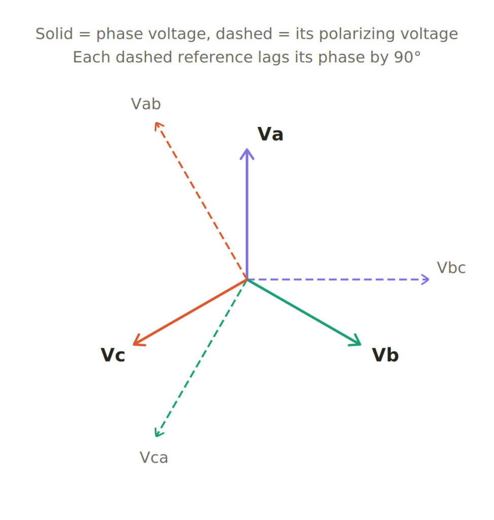
The full quadrature phasor set. Each dashed polarizing voltage lags its solid phase voltage by 90°. Because Vbc is built only from phases B and C, it stays healthy during an A-phase fault.
The reason this connection stays alive during a close-in phase-to-earth fault is visible directly from the phasors. When an A-to-ground fault collapses Va at the relay, Vbc is unaffected because it depends only on the two healthy phases:

Figure 3 — Close-in A-G fault. Self-polarization loses its reference (the red, collapsed Va), but the cross-polarized reference Vbc (green) remains at full magnitude, so the directional decision is preserved exactly where self-polarization fails.
Why 90° rather than 30° or 60°
Historically, other cross-polarizing connections were used. In the 30° connection the A-element is polarized by Vac; in the 60° connection by a combination such as Vac + Vbc. Comparing the reference each scheme provides for the A-phase element makes the winner obvious:
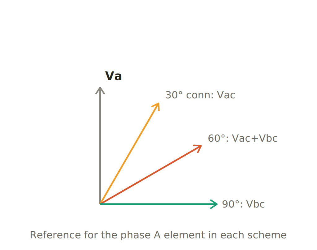
Figure 4- Reference for the phase-A element in each scheme. Only the 90° connection uses a reference (Vbc) that contains no component of the faulted phase.
The structural difference is decisive: the 90° reference is the only one containing no trace of the faulted phase. Vac, used by the 30° connection, includes Va itself, so it partially collapses and rotates during an A-phase fault. And the condition the directional element is designed to survive. The 60° connection carries the same contamination. Analysis across all fault types and realistic source-impedance angles also shows the quadrature pairing keeps the fault current farthest from the zero-torque boundary, giving the widest secure margin. This is why virtually all modern numerical relays default to the 90° connection with a selectable RCA of 30° or 45°.
The remaining blind spot: memory polarization
Cross-polarization has one weakness it cannot solve by itself. That is a bolted three-phase fault at the relay terminals, which collapses all three voltages simultaneously and leaves no healthy reference anywhere. Numerical relays cover this with memory polarization. The relay continuously tracks the positive-sequence voltage phasor. When the measured voltage drops below a threshold typically a few percent to about 10% of nominal. The relay switches to the stored pre-fault phasor as its reference. That stored phasor is rotated forward at system frequency to keep it in step. It is used for only a short interval, usually of the order of a second. That is long enough for the instantaneous directional element to make a secure decision on a close-in three-phase fault before the memory expires.
Supervising the reference: VT fuse failure
Because cross-polarization depends entirely on VT signals, a lost or corrupted voltage reference could produce a false direction decision. Relays therefore include a VT fuse-failure / loss-of-potential (LOP) detector. Which recognises when the voltage input has been lost for a reason other than a genuine fault. And blocks or de-directionalizes the affected elements, preventing maloperation.
Zero-sequence polarization: directional earth-fault protection (67N)
Phase voltages make poor references for sensitive earth-fault protection, because a high-resistance ground fault barely disturbs them. The earth-fault directional element instead compares zero-sequence quantities, which only appear during ground faults. There are two common sources of reference, and relays often use both.
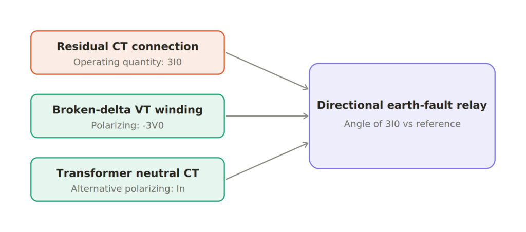
Figure 5: Inputs to a directional earth-fault relay. The operating quantity is the residual current 3I₀; the reference can be the residual voltage −3V₀ (broken-delta VT) or the transformer neutral current Iₙ, or both together.
Voltage polarization (-3V0): The operating quantity is the residual current 3I₀, obtained either from the three phase CTs paralleled in a residual (Holmgreen) connection or from a core-balance CT. The polarizing quantity is the residual voltage 3V₀, taken from a broken-delta (open-delta) VT secondary, or simply computed internally by a numerical relay from the three measured phase voltages.
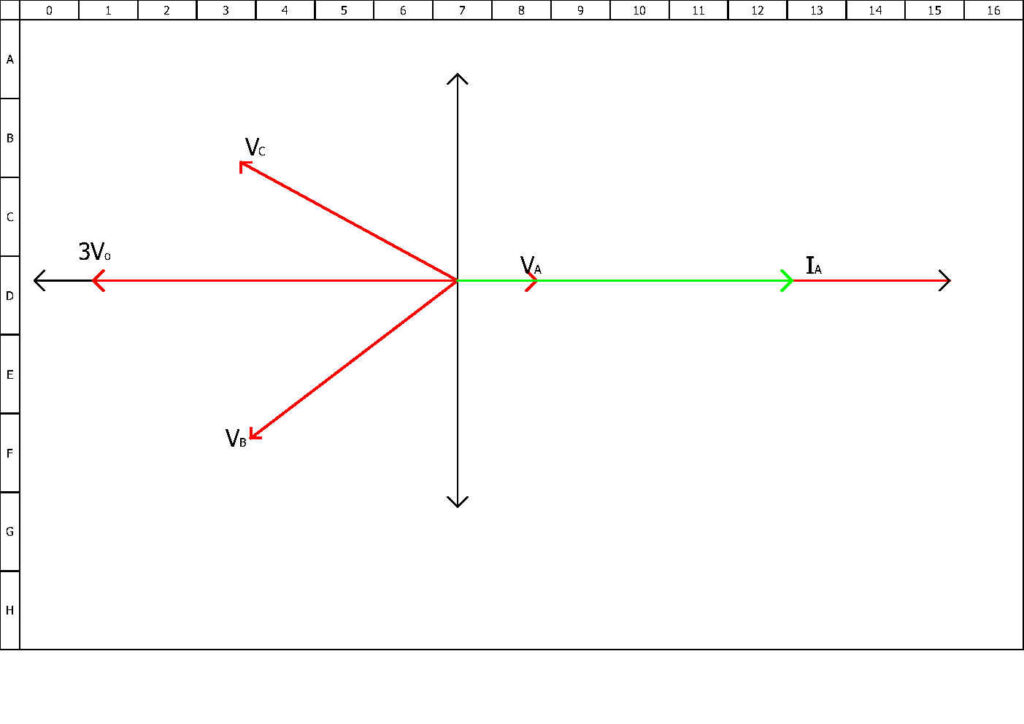
During a ground fault, the zero-sequence voltage at the relay equals −I₀·Z₀(source), so the relay actually references −3V₀; with a typical RCA in the region of −45° to −60° (I₀ lagging −V₀), a forward ground fault falls in the operate zone. The strength of this method is that 3V₀ is largest exactly where the phase voltages are most disturbed. So there is no dead zone for close-in ground faults.
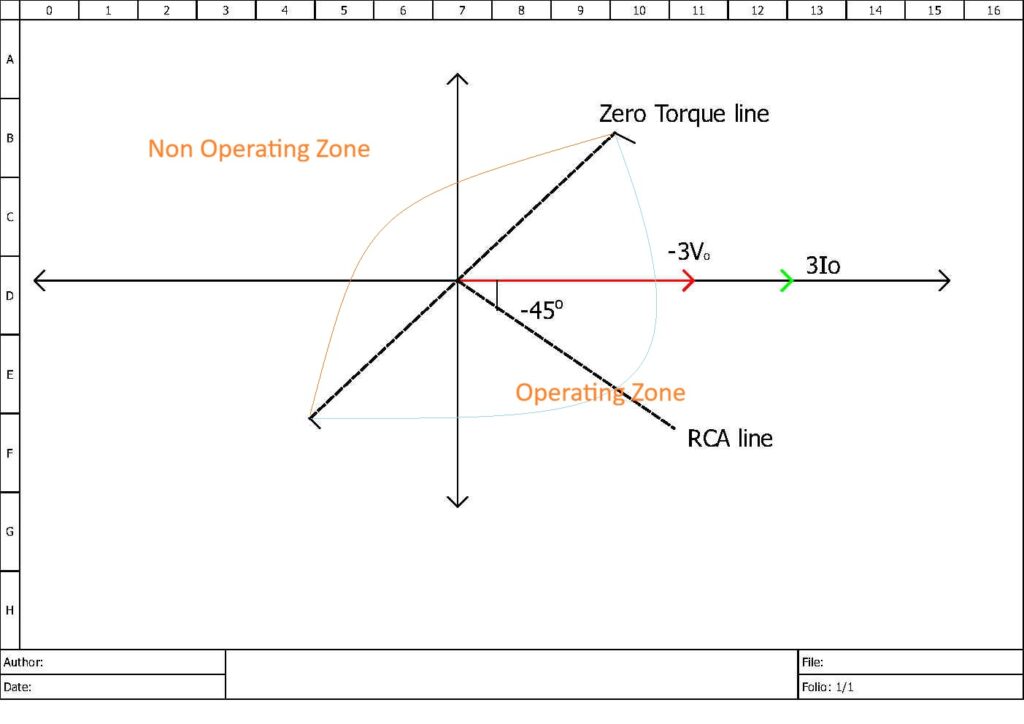
Its limitation is the opposite extreme: at a relay located close to a strongly grounded source, 3V₀ can be very small for remote faults.
Current polarization (IN): Where a suitable grounded transformer exists at the substation, a CT in the transformer’s neutral-to-ground connection provides a polarizing current. Whose direction is essentially fixed regardless of where the fault is. The neutral current always flows up from the earth into the system. The relay then compares the angle of the line residual current 3I₀ against this neutral current.
Current polarization is very robust where it is available, but it carries traps. It can be invalid for certain autotransformer configurations, where the neutral current may reverse depending on the ratio of zero-sequence impedances. And it obviously requires a grounding source at that station. A delta tertiary winding CT(current-transformer) can serve as an alternative source.
Dual polarization
Many relays offer dual polarization, using both −3V₀ and Iₙ together. So that if one reference is weak small 3V₀ near a strong source, or an unreliable neutral current for a remote fault, the other carries the decision. This gives dependable earth-fault directionality across a wider range of fault locations than either source alone.
Negative-sequence Polarization
Modern numerical relays increasingly offer a directional element that compares negative-sequence current I₂ against negative-sequence voltage V₂. The Relay uses the relationship V₂ = −I₂·Z₂. It is valuable in two situations where zero-sequence methods struggle.
The first is parallel lines with strong zero-sequence mutual coupling. Induced 3V₀ from a healthy parallel circuit can mislead a zero-sequence directional element into declaring the wrong direction. As negative-sequence networks have negligible mutual coupling, so the I₂/V₂ comparison is immune to this effect. The second is systems where the zero-sequence source is isolated from the relay by a delta winding, leaving little usable 3V₀ or 3I₀.
The limitation is that negative-sequence directionality only works for unbalanced faults and needs enough I₂ and V₂ magnitude to make a secure decision. Relays therefore apply minimum thresholds, and some implement impedance-based (Z₂) directional logic rather than a pure angle comparison.
Worked Example an A-G fault through a 90° Cross-polarized Element
To make the directional decision concrete, consider a relay looking into a feeder, with the standard quadrature connection and an RCA of 45°. All angles are referenced to the pre-fault Va.
Pre-fault voltages (phase values, 1 pu magnitude):
Va = 1∠0° Vb = 1∠−120° Vc = 1∠+120°Polarizing quantity for the A-element:
Vbc = Vb − Vc = (1∠−120°) − (1∠+120°) = √3 ∠ −90°Magnitude √3, lagging Va by exactly 90°; precisely as the phasor star in Figure 2 predicts.
Forward fault
Take a fault loop (source plus line to the fault point) with an impedance angle of 70°, typical of an overhead line. The fault current is:
Ia = 5 ∠ −70° pu(The magnitude is arbitrary; the directional element only cares about angle.) The relay advances Vbc by the RCA to form the maximum-torque reference:
Ref = √3 ∠ (−90° + 45°) = √3 ∠ −45°The directional test asks whether Ia lies within ±90° of that reference:
angle(Ia) − angle(Ref) = −70° − (−45°) = −25°Only 25° off the maximum-sensitivity line, deep inside the operate half-plane, with a 65° margin to the nearest zero-torque boundary. The relay declares forward and releases the overcurrent element.
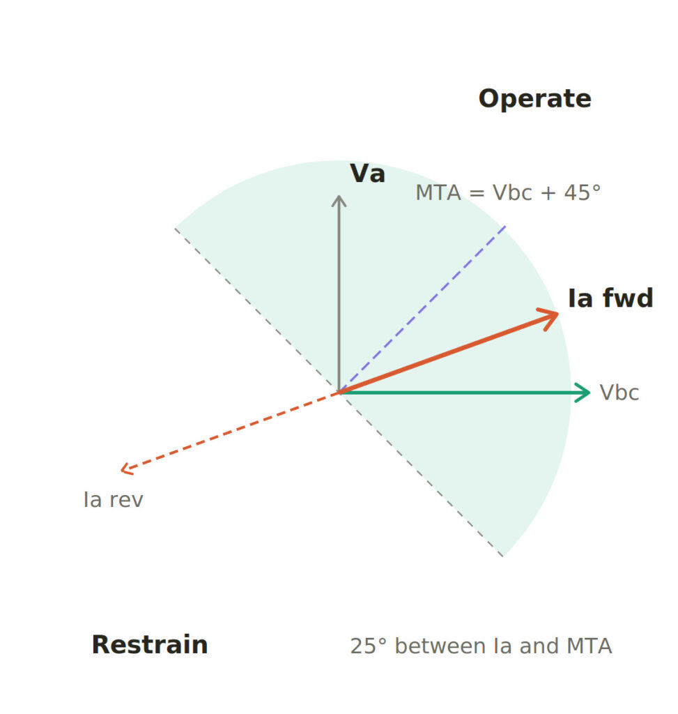
Figure 6: Worked example, drawn to scale. Advancing Vbc by the 45° RCA places the maximum-torque line so that a realistic forward fault current lands 25° away from it, comfortably inside the operate region. The reverse current sits 180° away, in the restrain region.
The same fault, reversed
If an identical A-G fault occurs behind the relay, the current through its CTs flips 180° with the same magnitude, opposite direction:
Ia = 5 ∠ (−70° + 180°) = 5 ∠ 110°
angle(Ia) − angle(Ref) = 110° − (−45°) = 155°   →  outside ±90°
The relay declares reverse and blocks tripping. Note that the decision hinged entirely on the current flipping, the polarizing voltage Vbc never moved. That stability is exactly what a good reference buys you.
Close-in bolted fault
Let Va collapse to 0.05∠0° (essentially zero at the relay terminals). Recomputing the reference: Vbc depends only on Vb and Vc. Which for a close-in A-G fault on a solidly grounded system remain near 1∠−120° and 1∠+120°. So Vbc ≈ √3∠−90°, unchanged, and the arithmetic of forward fault is identical means forward decision, full 65° margin. A self-polarized element attempting the same test with 0.05 pu of reference voltage would be below its minimum polarizing threshold and unable to decide at all. This single recomputation is really the entire argument for cross-polarization.
How Secure is the Margin?
Sweeping the fault angle across everything physically credible:
- a very resistive forward fault giving Ia ≈ ∠−20°: relative angle = −20 − (−45) = +25° → operate
- an almost purely reactive fault giving Ia ≈ ∠−88°: relative angle = −88 − (−45) = −43° → operate
To reach the zero-torque boundary, the forward current would have to either lead Va by more than 45° or lag it by more than 135°. Neither of which occurs in a real, resistive-inductive fault loop. Every reverse current sits 180° from its forward twin, so it inherits the same comfortable margin on the restrain side. Choosing RCA = 30° instead would place the reference at ∠−60° and simply shift the margins by 15° still secure, and better centred for systems whose fault angles run higher (more inductive).
The Healthy-phase Elements Stay Quiet
It is worth confirming the B and C-elements do not nuisance-operate during the A-G fault. They carry only load current, say Ib = 0.3∠−150° for a lagging load. The B-element references Vca advanced by 45°: Vca = √3∠150°, giving a reference at ∠195°. The relative angle is −150° − 195° = −345° ≡ +15°, which is inside the directional zone correctly. Because load flow is in the forward direction. Direction alone trips nothing: the B-element’s overcurrent stage sees only 0.3 pu, far below pickup, so it stays silent. This is the essential division of labour, the directional unit answers only “which way,” and the overcurrent unit answers “is it a fault.”
A Complete 67 / 67N Scheme
In practice, a full directional overcurrent scheme combines these methods according to their strengths:
- Phase elements (ANSI 67) use the 90° cross-polarized connection with memory polarization as backup for close-in three-phase faults, and an RCA of 30° to 45°. VT fuse-failure supervision guards the reference.
- Earth-fault elements (ANSI 67N) use zero-sequence voltage polarization (−3V₀), or dual polarization where a suitable neutral CT exists, with an RCA around −45° to −60° for solidly grounded systems.
- Negative-sequence directionality provides an alternative reference on mutually coupled parallel circuits, where zero-sequence polarization can be misled.
The directional decision then simply supervises an ordinary IDMT or definite-time overcurrent element. The relay only times out and trips if the fault is seen in the forward direction. That supervision is precisely what allows non-unit graded overcurrent protection to be applied to ring mains and parallel feeders. For the same networks where a plain, non-directional overcurrent relay could not coordinate at all.
Conclusion
Directional overcurrent protection adds a single missing dimension(direction) to a familiar and economical protection principle. The reliability of that added dimension rests almost entirely on the choice of polarizing quantity. Self-polarization is intuitive but blind to close-in faults; cross-polarization, particularly the 90° quadrature connection backed by memory polarization, solves the phase-fault problem robustly; zero-sequence polarization (voltage, current, or both) does the same for earth faults; and negative-sequence polarization covers the awkward cases of mutual coupling and delta-isolated sources. Understood together, they explain why a modern 67/67N relay makes such dependable directional decisions across every fault type a network can present.
Frequently Asked Questions
Your Attractive Heading
What is The ANSI/IEEE Standard Device Number for Directional Overcurrnt Protection?
The number 67 is the ANSI/IEEE standard device number for a Directional Overcurrent Relay. This is a universally recognized code in the power industry that identifies the function of a protective device.
What is the difference between ANSI 67 and 67N?
ANSI 67 is the directional phase-overcurrent element. It supervises the phase (line) current elements and is used for phase-to-phase and three-phase faults. ANSI 67N is the directional earth-fault (ground) element. It operates on residual current 3I₀ and handles phase-to-earth faults, usually with far greater sensitivity than the phase elements.
What is the Relay Characteristic Angle (RCA)?
The RCA called the Maximum Torque Angle (MTA) in electromechanical relays. This is the angle, measured from the polarizing quantity, at which the operating current produces the strongest operating tendency. It effectively rotates the operate/restrain boundary so that a typical fault current sits squarely in the middle of the operate region. Typical settings are 30° to 45° for phase elements and around −45° to −60° for earth-fault elements on solidly grounded systems.
Why can’t an ordinary overcurrent relay work on a ring main or parallel feeders?
A plain overcurrent relay responds only to current magnitude, not direction. On a ring main or between parallel circuits, fault current of similar magnitude can flow either toward a fault the relay should clear or toward one a different relay should clear. Without a way to distinguish the two, the relays cannot be graded to trip selectively. Adding a directional element resolves the ambiguity, which is why 67/67N is essentially mandatory on these network topologies.
What is the difference between self-polarization and cross-polarization?
Self-polarization references each phase-current element to its own phase voltage (Ia to Va, and so on). It is simple but fails for close-in faults, because the faulted phase’s voltage collapses and leaves no usable reference. Cross-polarization instead references each current to a voltage derived from the two healthy phases. For the A element, the line voltage Vbc, which stays close to normal during a single-phase fault. This eliminates the close-in dead zone and is why cross-polarization dominates practical phase-fault relaying.
What is memory polarization and when is it needed?
Memory polarization covers the one case cross-polarization cannot — a bolted three-phase fault at the relay terminals, which collapses all three voltages at once. The relay continuously tracks the positive-sequence voltage phasor, and when the measured voltage drops below a threshold it substitutes the stored pre-fault phasor (rotated forward at system frequency) as the reference for a short interval, typically of the order of a second. That is long enough for the instantaneous element to make a secure directional decision before the memory expires.
What happens if the VT fuse fails or the relay loses its polarizing voltage?
Because cross-polarization and voltage-polarized earth-fault elements depend on VT signals, a lost or corrupted voltage could produce a false direction decision. Relays therefore include a VT fuse-failure / loss-of-potential (LOP) detector that recognises when the voltage input has been lost for a reason other than a genuine fault, and blocks or de-directionalizes the affected elements to prevent maloperation.