
Large interconnecting transformers that link two high-voltage networks are very often built as autotransformers with the vector group YNa0d1. The networks may be 400/230 kV, 400/230 kV, 765/400 KV or 230/132 kV systems. The designation appears on nearly every grid-intertie nameplate, yet it condenses a surprising amount of information. How the windings are physically connected? How the voltages of the three windings are phase-displaced relative to one another. Also why the machine is suited to bulk power interconnection. This article unpacks the symbol piece by piece. First walks through the winding arrangement and phasor diagram. Then looks at where and why YNa0d1 autotransformers are used.
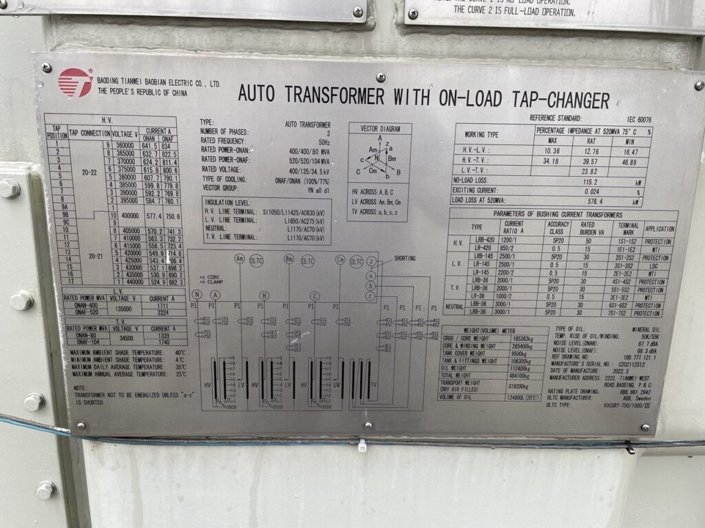
Decoding Autotransformer Vector Group YNa0d1
Vector group notation, standardized in IEC 60076-1, lists the windings in descending order of voltage. Capital letters describe the highest-voltage winding. Where lowercase letters describe the lower-voltage windings. Besides, the digits give the phase displacement of each lower-voltage winding relative to the HV winding. Which uses the familiar clock convention, where each clock hour represents 30 degrees of lag.
For YNa0d1, reading left to right:
Firstly, YN means the high-voltage winding is star (wye) connected, and the neutral point is brought out to a bushing. In an autotransformer this neutral is normally solidly grounded. Which matters both for insulation design and for zero-sequence behavior, will be discussed later.
Then a0 means the medium-voltage winding is auto-connected to the HV winding. Also its voltage is in phase with the HV voltage (clock position 0, i.e., 0° displacement). The lowercase “a” is the distinguishing mark of an autotransformer. The MV output is tapped from a point on the same physical winding structure as the HV instead of a galvanically separate secondary (which would be written “yn0”). Because the MV voltage is literally a portion of the HV phase voltage. The two are inherently and exactly in phase. An autotransformer between star-connected systems cannot produce anything other than a 0° shift.
Finally, d1 indicates a third galvanically separate winding connected in delta, whose line voltage lags the HV line voltage by 30° (clock position 1). This is the tertiary or stabilizing winding. Which is typically rated at 11 kV, 33 kV, or similar, and often sized at roughly one-third of the throughput rating.
So the autotransformer vector group YNa0d1 describes a three-winding transformer. Which includes an earthed-star HV winding, an auto-connected MV winding in phase with it, and a delta tertiary displaced by −30°.
Winding Connection of Autotransformer Vector Group YNa0d1

The physical construction is what makes an autotransformer economical. Each phase carries two winding sections on the core limb:
The common winding stretches from the neutral point up to the MV terminal. The series winding continues from the MV terminal up to the HV terminal. The HV circuit therefore uses the series and common windings in series (neutral → common → series → HV terminal), while the MV circuit uses only the common winding (neutral → common → MV terminal). All three phases share a single neutral, which is brought out as the YN terminal and solidly earthed.
Because part of the winding is shared, power transfers between the HV and MV systems partly by direct electrical conduction and partly by magnetic induction. The transformer’s core and windings only need to be built big enough for the magnetically transferred portion of the power. This portion is known as the co-ratio:
Co-ratio = (V_HV − V_MV) / V_HV = 1 − 1/k, where k is the transformation ratio.
For a 400/220 kV autotransformer, the co-ratio is (400 − 220)/400 = 0.45. The frame size, copper mass, losses, and impedance correspond roughly to a conventional two-winding transformer of only 45% of the throughput rating. This is why an autotransformer rated 315 MVA of throughput can be built on the frame of a ~140 MVA conventional unit. The saving is dramatic when the voltage ratio is close to unity and evaporates as the ratio grows, which is why autotransformers are rarely used beyond a ratio of about 3:1.
The tertiary delta winding sits on the same core limbs but is electrically isolated from the series/common structure. It is usually the innermost winding, closest to the core.
Phasor Diagram of A Three Winding YNa0d1 Autotransformer
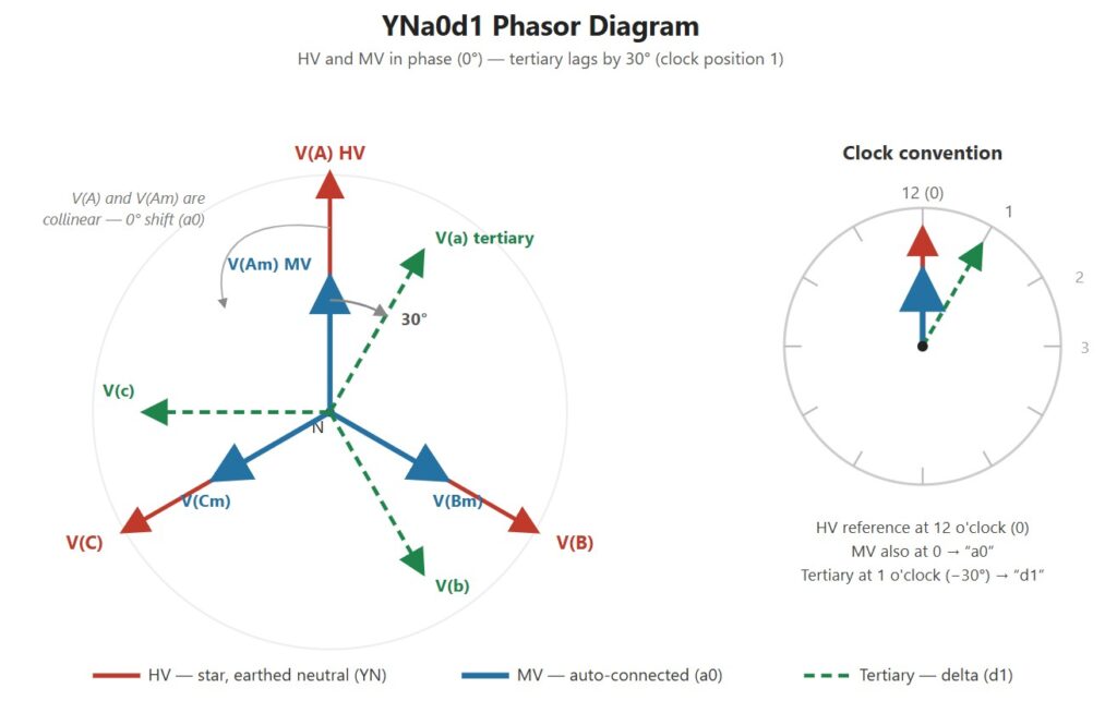
Take the HV phase voltage of phase A as the reference, pointing at 12 o’clock.
HV and MV phasors: Since the MV voltage is simply the voltage across the common winding. That means MV is a segment of the same phase HV winding. So, the MV phasor for phase A points in exactly the same direction as the HV phasor. Only difference is just shorter in proportion to the turns. The three HV phasors and three MV phasors form two concentric stars sharing the same neutral point and the same angular positions. This is the “a0” in the symbol: zero displacement, clock position 0.
Tertiary phasors. The delta winding is wound so that each delta leg links flux in a way that places its line voltage 30° behind the corresponding HV line voltage. On the clock face, if HV line voltage sits at 12 o’clock, the tertiary line voltage sits at 1 o’clock. Hence the tertiary symbol is “d1”. This −30° shift is not incidental; it is the natural displacement that arises when a delta winding is paired with a star winding. But choosing d1 (rather than d11, which leads by 30°) is simply a matter of standardized coil polarity and terminal labeling. Though d1 and d11 tertiaries exist in practice. D1 is the common convention in IEC influenced grids such as those in South Asia.
So, remember that in any star/delta pair, the delta line voltage is displaced by an odd multiple of 30° from the star line voltage. In any star/star or auto pair, the displacement is an even multiple (usually 0°). YNa0d1 obeys both rules.
Why Delta Tertiary Winding Used in YNa0d1
While star-star (or auto-connected) transformers with a three-limb core has a few well-known vulnerabilities. Adding a delta tertiary winding completely solves these problems.
Third-harmonic magnetizing current: The magnetizing current of a transformer is non-sinusoidal and rich in third harmonics. In a star winding with no delta anywhere, these triplen harmonics have no circulating path. The flux becomes distorted, and the phase voltages develop a pronounced third-harmonic component. The closed delta provides a low-impedance loop in which triplen-harmonic currents circulate freely keeping the exact flux. Therefore the output voltage becomes nearly sinusoidal.
Zero-sequence impedance stabilization: During an earth fault on either the HV or MV network, zero-sequence current must flow. The delta tertiary acts as a zero-sequence “short circuit” seen from either star winding. The zero-sequence ampere-turns in the star windings are balanced by circulating current in the delta. This gives the autotransformer a low, stable, predictable zero-sequence impedance. Which keeps earth-fault currents high enough for protective relays to detect reliably. Also limits neutral-point voltage displacement on the healthy phases.
Load balancing: Unbalanced single-phase loads on the MV side are partially rebalanced by the circulating tertiary current.
A usable third voltage: Beyond its stabilizing role, we connect load to the tertiary. A loaded tertiary may supply station auxiliaries, feeds shunt reactors or capacitor banks for reactive power compensation. In some installations connects a synchronous condenser or STATCOM. When the tertiary is loaded, its terminals are brought out through bushings.
Applications of YNa0d1 Autotransformer
YNa0d1 is essentially the default vector group for grid interconnecting transformers between two effectively-earthed transmission networks of the same phase reference. Which includes:
EHV interties: The 765/400 kV, 400/220 kV, 500/220 kV, 345/138 kV autotransformers linking transmission tiers within one synchronous grid. Because both networks are star-earthed and must remain in phase with each other. The 0° displacement of the auto connection is not just economical, it is required.
Bulk substation step-down: 220/132 kV and 132/66 kV autotransformers in sub-transmission, where the modest ratio makes the auto connection highly economical.
The requirement that both systems share a common earthed neutral is fundamental. Since HV and MV are galvanically connected. The neutral must be solidly earthed to fix insulation levels. Which prevent HV disturbances from imposing dangerous overvoltages on the MV system. YNa0d1 units are therefore used only between effectively earthed networks.
Parallel Operation of Autotransformer YNa0d1 Vector Group
Transformers can be paralleled only if their vector groups produce identical phase displacement on corresponding terminals. A YNa0d1 autotransformer can connect parallely directly with another YNa0d1 unit. This thing can do also with a conventional YNyn0d1 three-winding transformer, since both present 0° displacement between HV and MV. It cannot be paralleled with any group producing a ±30° HV–MV shift (YNd1, Dyn11, etc.). Attempting to do so would drive an enormous circulating current limited only by the transformer impedances.
Advantages and Limitations of YNa0d1 Autotransformer
The advantages flow from the shared winding: for a given throughput, an autotransformer is smaller, lighter, and cheaper than a two-winding equivalent. Also advantages with lower copper and iron losses, better efficiency, smaller excitation current, and better inherent voltage regulation. Its lower series impedance also reduces voltage drop under load.
The limitations flow from the same source. The galvanic HV–MV connection means an insulation failure or transferred surge on the HV side reaches the MV network directly, so surge protection and insulation coordination need extra care. The lower impedance raises short-circuit current levels, sometimes requiring current-limiting measures. The solidly earthed common neutral is mandatory, not optional. And the economic advantage shrinks rapidly as the transformation ratio increases, effectively confining autotransformers to ratios below roughly 3:1.
YNa0d1 reads as earthed-star HV winding, auto-connected MV winding in phase with it, and a delta tertiary lagging by 30°. The auto connection delivers the size and cost savings that make EHV interconnection economical. The earthed neutral and 0° displacement make the unit suitable for tying together effectively earthed networks that must stay in phase. Besides, the delta tertiary suppresses third-harmonic distortion, stabilizes zero-sequence impedance for reliable earth-fault protection. Also provides a convenient medium-voltage terminal for reactive compensation and station supply. That combination explains why, wherever two transmission voltage levels of one synchronous grid meet, a YNa0d1 autotransformer is very likely doing the work.